Connector Board
The Connector Board is the central hub of your PiTrac. It handles connections between the Raspberry Pi computers and the strobe light while also providing regulated power for the IR LED array.
Board Versions
V3 - (Current)
V3 Connector further refines what we learned with V2 while also moving to a thru-hole design.
What changed from V2:
- All thru hole construction.
- Remove ineffective 555 timer circuit.
- Full control of LED current including ADC for calibration.
V2 - Dual Pi5 Connector Board (Deprecated)
The V2 board is a complete redesign focused on simplification and cost reduction.
What it does:
- Connects two Pi units safely with shared power (no opto-couplers needed)
- Provides adjustable boost converter output (~15V to ~42V range)
- Stores energy in large caps for strobe pulses
- Adjustable LED current draw (supports various IR LED configurations)
- Hardware-enforced 10% duty cycle for thermal protection (dual 555 timers)
- Replaces several power supplies with a single +5V input
What changed from V1:
The original board was designed to connect two Raspberry Pi units with separate AC/DC supplies and opto-coupler isolation. This protected them from power switching issues that can kill a Pi. The V1 board works, but needed better integration to reduce system cost.
V2 moves to a single AC/DC supply, eliminating the need for opto-couplers by safely sharing power between Pi units. The integrated boost converter and LED driver circuit replace several external power supplies. All told, you go from multiple power supplies (including the LED driver) to a single +5V supply.
V1 - Original Connector Board (Deprecated)
If you have a V1 board, it works fine. Just follow V1-specific instructions. If you’re building new, use V2.
IRLED
Original LED array is becoming expensive and challenging to source, this provides a custom replacement using LEDs available in distrobution.
Board Versions
IRLED2 - (Current)
What changed from OG: Fixed footprint mistake for last minute LED change.
IRLED - (Depreciated)
Only work with more expensive LED PN SST-10-IRD-B90H-S810 [https://www.digikey.com/en/products/detail/luminus-devices-inc/SST-10-IRD-B90H-S810/13557593] Uses 10 LEDs in a 5S2P configuration to provide substantial illumination.
Ordering the PCB
Where to Order
Any decent PCB fabricator can make this board. Two popular options:
- JLCPCB - https://jlcpcb.com
- PCBway - https://www.pcbway.com
Both have easy file upload and offer assembly services.
Save Money: Check Discord #pitrac-stuff-for-sale before ordering. Community members often have spare boards at cost.
Fabrication and Assembly Files
There are three different PCBs filesets, the combined PCB has two BOM variants determining how much of the assembly you want done by the vendor. For smaller order quantities (without assembly) the seperate PCB files is likely to be cheaper.
V3 Connector Only
Hardware/Fabrication Files/V3 Connector Only Gerbers.zip
Assembly of V3 Connector with vendor not recommended
Hardware/Assembly Files/V3 Connector Only/V3 Connector Only Assembly/*
IRLED2 Only
Hardware/Fabrication Files/IRLED2 Only Gerbers.zip
Hardware/Assembly Files/IRLED2 Only/IRLED2 Only Assembly/*
V3 Connector + IRLED2
There are two BOM variants due to it being a panel of two PCBs. It is recommended that you only use an assembler for the surface mount IR LEDs. It is more cost effective generally to purchase the components and assemble the entirely thru-hole V3 connector by yourself.
Hardware/Fabrication Files/V3 Connector + IRLED2 Gerbers.zip
Assemble IRLED2 (Recommended)
Hardware/Assembly Files/V3 Connector + IRLED2/IRLED2 Assembly/*
Assemble V3 Connector + IRLED2 Assembly of V3 Connector with vendor not recommended
Hardware/Assembly Files/V3 Connector + IRLED2/V3 Connector + IRLED2 Assembly/*
Ordering Process
-
Upload the Gerbers - Upload Gerbers.zip to JLCPCB or PCBway
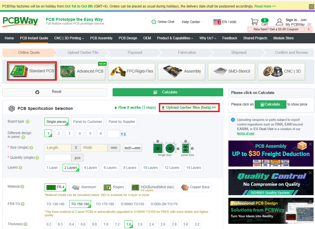
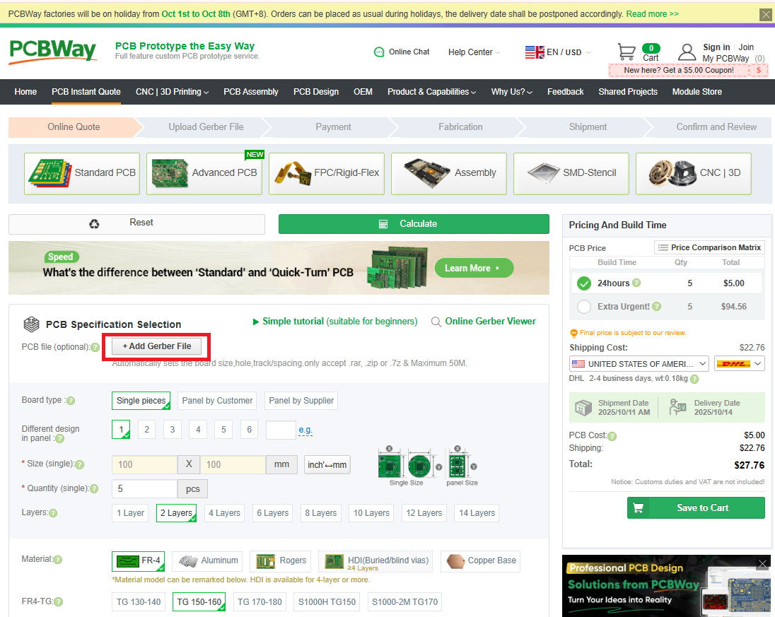
- Board specs - Update the following attribute:
- Thickness: 0.8mm
- Surface Finish -
- Ensure set to “HASL Lead-Free”
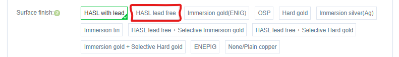
Use lead-free solder for assembly, so get a lead-free board finish.
- Quantity - Minimum order is usually 5 boards. Only 1 V3 Connector and 1 IRLED are required for a PiTrac build.
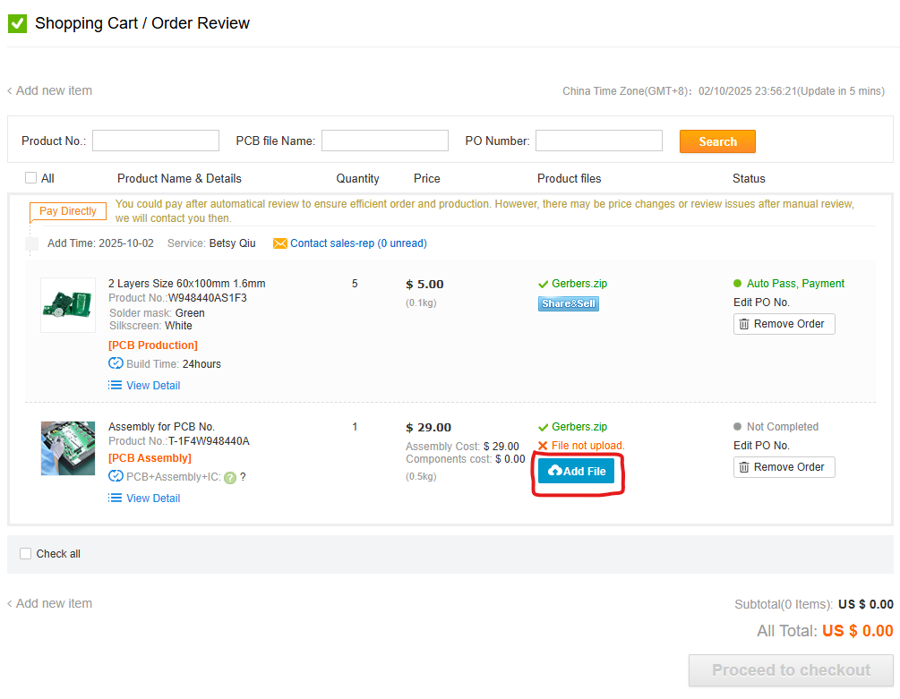
Assembly Service (Optional)
Don’t want to solder? Both JLCPCB and PCBway offer assembly services.
Select Assembly Service:
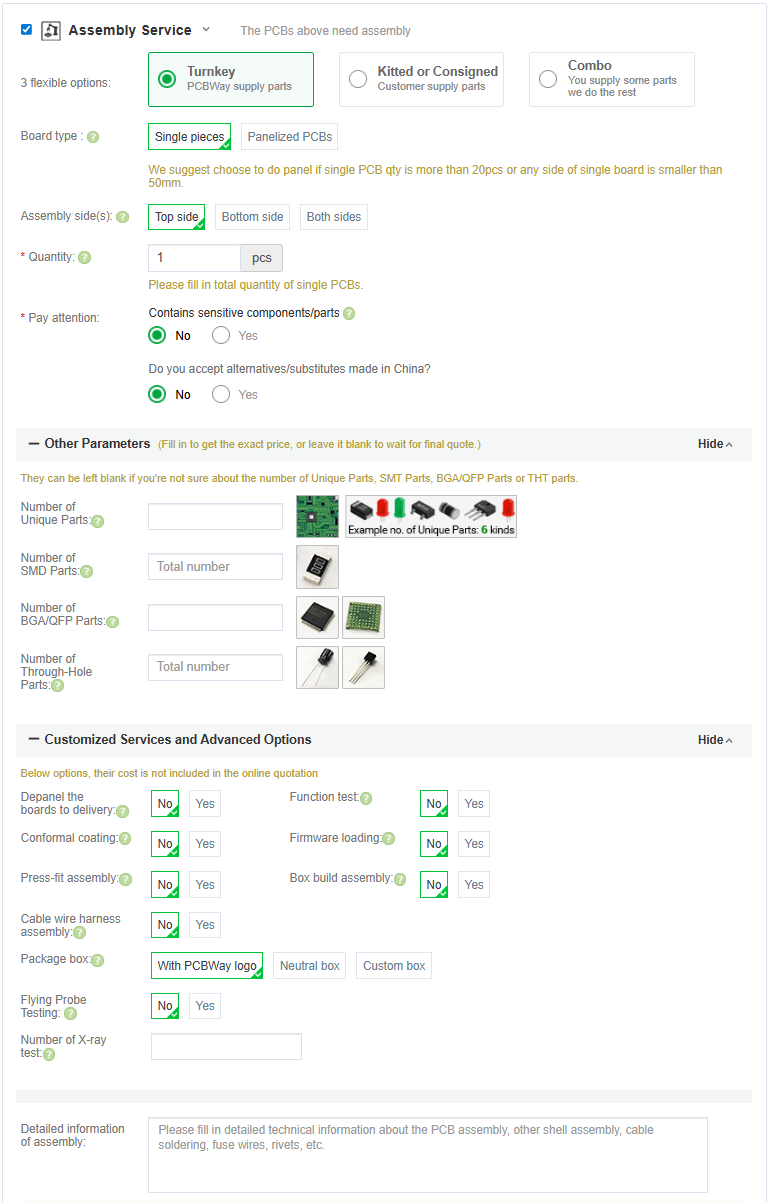
The fab house sources components, solders everything, and ships you a completed board. Costs more, but saves significant time.
Once you have added the board with assembly to your cart you will need to provide the information they need for assembly.
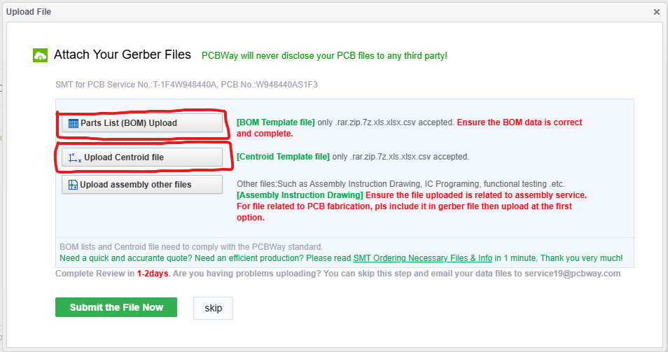
Component Sourcing
Bill of Materials
Complete BOM with Digikey links: Parts List
Assembly
Difficulty Assessment
Skill Level: Beginner / Intermediate
Time estimate:
- First build: 2-4 hours
- With experience: 1-2 hours
If you’re a true novice at soldering, some of it will take time.
Assembly Tips
- Order matters:
- DIP-8 Packages first (U1, U3, U5, U6)
- Resistors
- Capacitors
- MOSFETs, LDO etc.
- Connectors
- Before power-up:
- Check for solder bridges with multimeter
- Verify no shorts between power and ground
- Double-check component orientation (ICs, diodes, polarized caps)
Board Configuration
After assembly, must run current calibration before you will be able to capture shots.
Test Points
TP2 - Ground reference (use for all DC measurements)
TP1 - +5V Input TP3 - LDO Output TP4 - Current Sense TP5 - Gate Drive / Strobe Input TP6 - DAC Output Voltage
Connections
Power Input
- J1: 5V input from Meanwell LRS-75-5 (screw terminals)
Power Output
- J2/J5: USB-C ports for Pi power (5V)
Pi GPIO
- J3: 8-pin GPIO header for control signals (see below for Connection Guide for Raspberry Pi 5)
LED Output
- J4: Regulated high-voltage output to IR LED array (screw terminals)
- Current adjustable with DAC (U5)
Optional
- J6 (USB-A): Originally for LED strip, but Pi5 has USB 2.0 ports already - this is redundant
Connection Guide for Raspberry Pi 5
| V3 Connector Board | Raspberry Pi 5 |
|---|---|
| GND | GND (Pin 39) |
| DIAG | GPIO 10 (Pin 19) |
| CS0 | GPIO 18 (Pin 12) |
| MOSI | GPIO 20 (Pin 38) |
| MISO | GPIO 19 (Pin 35) |
| CLK | GPIO 21 (Pin 40) |
| CS1 | GPIO 17 (Pin 11) |
| V3P3 | 3V3 (Pin 1) |
| Global Shutter Camera 2 | Raspberry Pi 5 |
|---|---|
| Trig+ | GPIO 25 (Pin 22) |
| Trig- | GND (Pin 20) |
| V3 Connector Board | V3 IRLED Board |
|---|---|
| VIR+ | VIR+ |
| VIR- | VIR- |

Configuring PiTrac
You’ll need to tell PiTrac which version of the Connection Board you are using. This is done in the Configuration screen in the UI.
Before you run the PiTrac system for the first time, set the board type appropriately here: 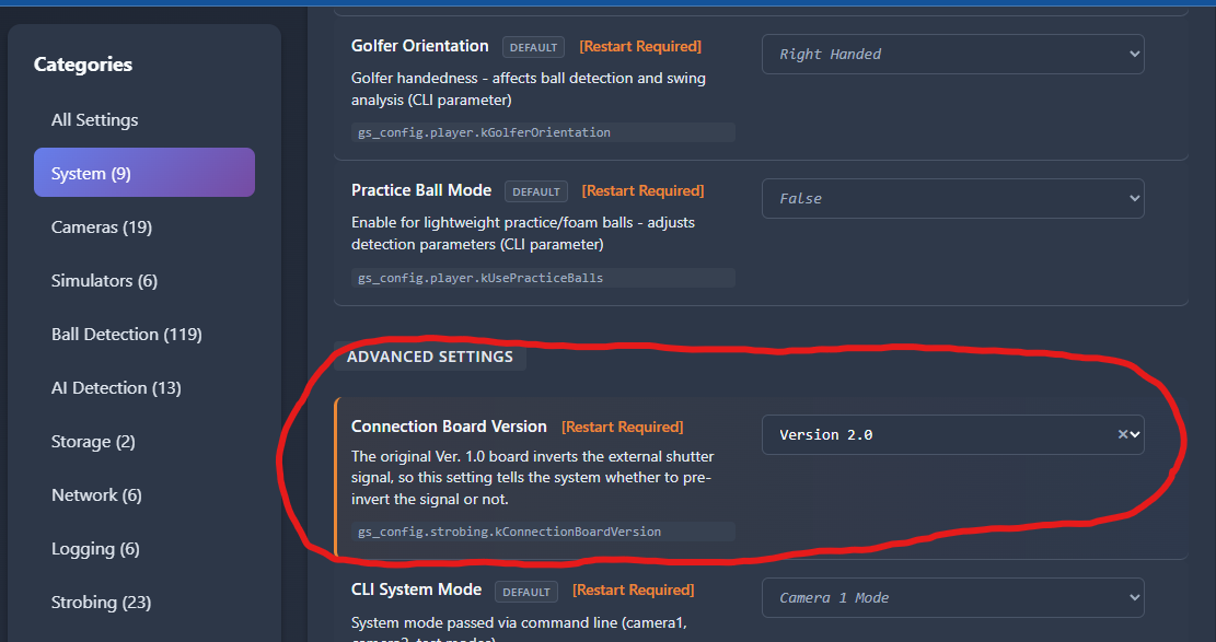
Note that the current default value is for the Version 1.0 board.
Design Files
Full design documentation:
Hardware/KiCad Source Files/*
KiCAD files are editable if you want to modify the design.