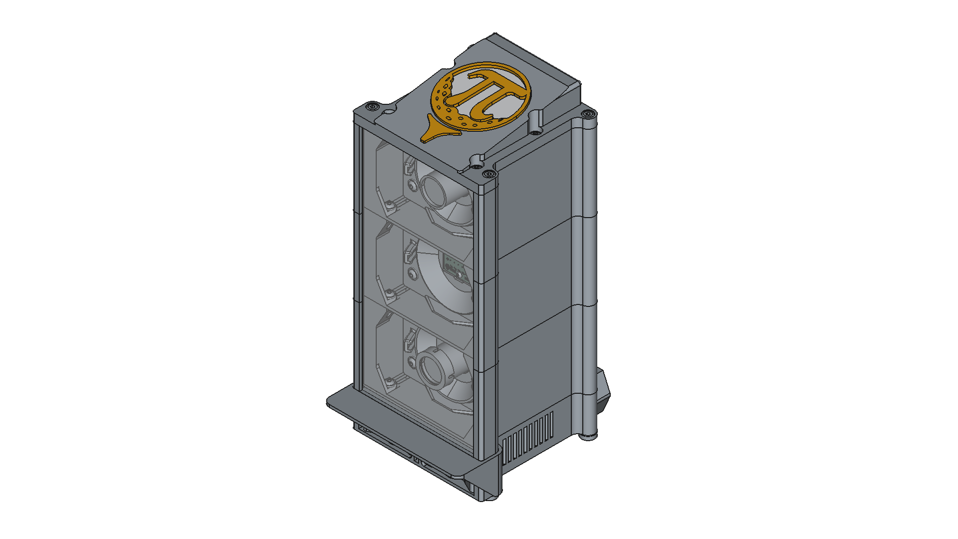
V3 Enclosure
Folder overview:
PiTrac/3D Printed Parts /Enclosure Version 3/
├─ Assembly/          # FreeCAD Assembly files
   └─ Assembly4/      # .FCStd and .svg assembly files
├─ Assets/            # general supporting material
│  └─ Part Pictures/  # Images for buildplate-orientation
└─ Part/
   ├─ Misc/           # .FCStd files for  CAD supporting material
   ├─ Calibration Rig/# .stl, .stp and .FCStd files for the calibration rig
   ├─ Purchase/       # .stp and .FCStd files for purchased parts
   └─ Print/          # .stl, .stp and .FCStd files for preferred design
      ├─ Legacy/      # .stl, .stp and .FCStd files for legacy parts
      └─ Variants/    # .stl, .stp and .FCStd files for design variants and mods.
         └─ Archive/  # .stl, .stp and .FCStd files for depreceated parts, likely to be deleted soon
Software
- FeeCAD v1.0.2, designed mainly in the Part Design Workbench
- Fasteners v0.5.44, for standard parts in the Assembly
- Assembly4 v0.60.6, for the Assembly files
Safety Disclaimer
Important: These 3D-printed parts are designed to house components connected to mains voltage (100–240V AC). Please observe the following safety precautions:
- Only place the assembled unit on a stable, non-flammable surface.
- Never leave the unit powered on and unattended.
- Keep out of reach of children and pets.
- Ensure proper ventilation around the power supply to avoid overheating. (not bedded into artificial turf)
- Handle electrical connections carefully and only if you are confident with mains electricity.
- Avoid cable damage: do not pinch wires or run them over sharp edges.
- Use proper fuses or circuit protection in the IEC connector.
- Always verify correct polarity and connections before powering on.
- Material choice matters: PLA is flammable; consider PETG or ABS for better heat resistance, ideally UL94 V-0 certified.
- Ensure print quality: no gaps or thin walls that could expose live components.
- Do not operate the unit in wet or humid environments.
- Keep all small parts secure and away from children or pets.
- Use appropriate tools for assembly and avoid sharp edges.
- Clearly mark modules and polarity where relevant to prevent mistakes.
- Take care not to drop screws or other components into the power supply during assembly.
- Always install the LinePower_Cover.stl to minimize the risk of electric shock.
Failure to follow these precautions can result in fire, electric shock, or personal injury. Print and use these parts at your own risk.
Main Informations
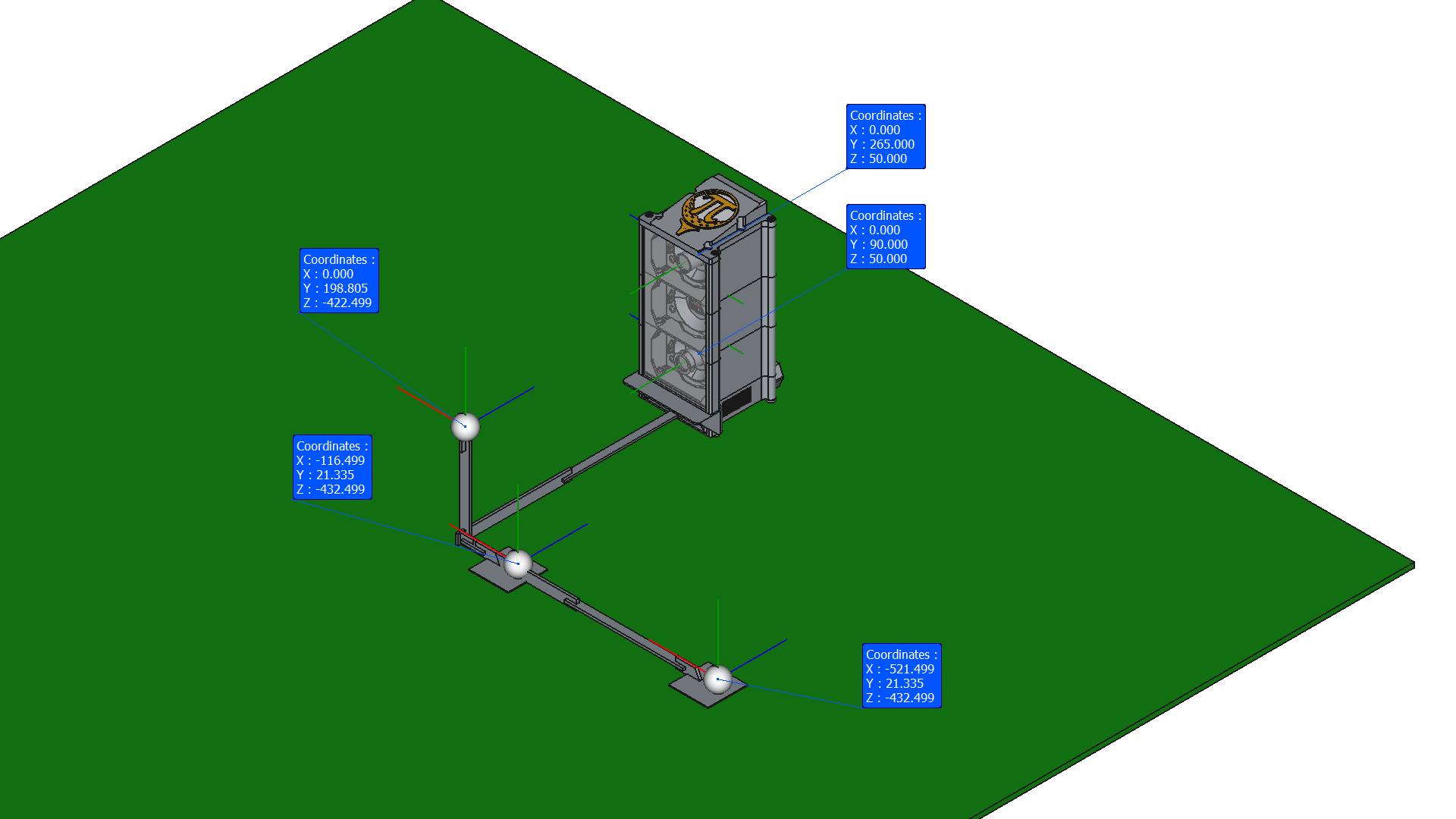 Calibration coordinates for the calibration rig:
Camera1 (tee - far back / long rig)
X: “-0.522” m
Y: “-0.241” m
Z: “0.483” m
["-0.522", "-0.241", "0.483"]
Camera1 (tee - near / short rig)
X: “-0.117” m
Y: “-0.241” m
Z: “0.483” m
["-0.117", "-0.241", "0.483"]
Camera2 (flight)
X: “0” m
Y: “0.109” m
Z: “0.473” m
["0", "0.109", "0.473"]
Assumtion: eyeball screen to front plane has a Z-distance of 30 mm (acc. to the assembly readme and drawings)
Requirements & Design Checklist
| Entry | Category | Requirement | Detail | Design-Action | Status |
|---|---|---|---|---|---|
| 1 | Structure | Adjustable feet | for leveling | M5 nut in foot, nominal is completely in, allows for a few mm adjustment | done |
| 2 | Optics | Reference interface to calibration rig | already established in V2 design | pocket in Stack_Module_PSU | done |
| 3 | Safety | UL94 V0 flame retardant filament | DIY PCB, mains voltage, high power LED, long runtimes | Cannot be controlled; pointed out in documentation / housing; Do not leave unattended label | - |
| 4 | Safety | IP40 IEC 60529 protection (ideally) | no fingers or tools should access critical areas | Rather IP20; all mains cables covered; no ventilation holes >5 mm near PSU; mains voltage not accessible → maybe IP40-ish | done |
| 5 | Safety | DIN VDE 0100 / 0701–0702 | min. 3 mm airgap, 5 mm structural gap on mains voltage | Safety margin between PSU and power socket for cables and airgaps | done |
| 6 | Safety | Cable strain relief | — | Not relevant for PSU due to housing design; peripheral and Pi cables uncritical | done |
| 7 | Safety | Ventilation holes (see IP40) | — | Holes in Stack_Module_PSU and Stack_Module_Cover | done |
| 8 | Safety | Mains voltage label | — | Already written on purchased power socket | done |
| 9 | Compatibility | Max footprint 175 × 175 mm | for small printers (e.g. Prusa Mini) | Largest part: 160 × 148 × 87.5 mm; room for brim or skirts | done |
| 10 | Compatibility | 2× Pi 4 with heatsink | — | 100 × 265 × 32 mm electronics space; USB cables may be limiting | done |
| 11 | Compatibility | 2× Pi 5 with heatsink | — | 100 × 265 × 32 mm electronics space; USB cables may be limiting | done |
| 12 | Compatibility | V1–V3 PCB clearance | — | V2mod and V3 tested | done |
| 13 | Compatibility | Compute Module | No longer applicable | — | — |
| 14 | Compatibility | Further cameras | — | — | — |
| 15 | Compatibility | Display | LCD / Pi display; HDMI interface required instead of Stack_Module_Cover | - | pending |
| 16 | Compatibility | Innomaker Cam | — | IMX296-MPI Eyeball, 6 mm | done |
| 17 | Compatibility | Pi Cam | — | PiCam Eyeball, 6 mm, 2.8 mm | done |
| 18 | Compatibility | Different lenses | — | Tested with 6 mm; 2.8 mm wide-angle designed | done |
| 19 | General | Pleasant to the eyes | — | Looks fine | done |
| 20 | Structure | Short BOM | — | Multipurpose parts: stack modules, screens, clamps | done |
| 21 | Structure | Easy assembly | — | To be confirmed by community | — |
| 22 | Optics | Adjustable cameras (pan/tilt) | — | Pan ±30°, tilt ±20°; suitable for long calibration rig; field of view likely obstructed for wideangle + full pan setup | done |
| 23 | Optics | Adjustable LED (pan/tilt) | — | Pan/tilt up to 30°; mostly unnecessary | done |
| 24 | Thermal | Free airflow for hot components | — | Ventilation holes bottom + outlet in cover (TBC); ventilated Stack_Module_PSU available | — |
| 25 | Optics | Stray light (shank shield) | reflections seen on one build | One-piece or 3-piece shield with separators; flush edges | done |
| 26 | Compatibility | Cam1–Cam2 relative position | close to V2 | X within a few mm | done |
| 27 | Compatibility | Floor–Cam2 position | close to V2 | X within a few mm; Z differs most | done |
| 28 | Structure | Thread inserts optional | — | No inserts needed | done |
| 29 | Optics | Rotation point at nodal point | — | Eyeball flange positions camera at rotation center; camera+lens specific | done |
| 30 | Compatibility | Designed in FreeCAD | open source / GitHub / .stl, .stp and .FCStd | .stl, .stp and .FCStd available | done |
| 31 | Compatibility | Parametric design | where relevant | On hold | |
| 32 | Cost | ≤ 1 kg filament | secondary priority | ~1.3 kg | failed |
| 33 | General | PiTrac logo | — | Large logo in Stack_Module_Cover; monochrome or insert available | done |
| 34 | Safety | PSU housing wall thickness | — | 3 mm | done |
| 35 | Liability | No official labels | no CE implication | — | done |
| 36 | Compatibility | LED strip traces | — | Ambient_LED_Screen supports LED strip | done |
| 37 | Structure | Shank shield thickness | 3/16″ or 1/4″ | 7 mm slot; 1/4″ fits; 3/16″ may need spacer | done |
| 38 | Compatibility | Metric & imperial screws | — | Currently metric only | — |
| 39 | Compatibility | Pi 5 with NVMe | — | Pi5_Carrier_3mmTroughHole: NVMe below Pi + brass studs | done |
| 40 | Compatibility | External USB & HDMI | Requires inverted Pi carrier (Bagpack style) | validation pending | done |
| 41 | Thermal | Optional fan in cover | Fan in Stack_Module_Cover | On hold | |
| 42 | Optics | Ring light for camera 1 | Adafruit #4433 | On hold | |
| 43 | Optics | Single COB LEDs (camera 1) | instead of LED strip; Focused illumination; avoid blinding | pending | |
| 44 | Compatibility | Battery pack instead of PSU | Li-ion pack with power management | On hold | |
| 45 | Compatibility | Status LEDs | RGB / NeoPixel-style indicators in cover | Design prepared with “Stack_Module_Cover_Insert, LED hw/sw integration pending | pending |
| 46 | Compatibility | Conventional camera mounts | Similar to V2 design for more adjustability | pan-tilt design in …/Variants | done |
| 47 | Compatibility | Fixed camera screens | Will allow for bigger field of view; saves material; only when a common best practice is established; lefty/righty specific | pending | |
| 48 | Compatibility | Off center eyeball_screens | To allow for a bigger pan for fast balls; lefty/righty specific | pending | |
| 49 | Compatibility | V3 Carrier | wire seperator for LED to avoid interference | design includes cable clips to sperate wires | done |
| 50 | Optics | LED Anti glare | visor for the ambient LED screen | Ambient_LED_Visor.stl | done |